Understanding Charge Profiles: CC/CV, Step, Pulse, Hybrid, and Adaptive
Thought Leadership
Charging a lithium-ion battery is a balancing act between speed, safety, cost, and long-term degradation. For OEMs building consumer electronics, power tools, e-mobility platforms, robotics, drones, and enterprise devices, the charging profile is one of the few levers that directly shapes user experience without forcing a battery redesign.
What looks externally like a simple rise in percentage is, internally, a tightly constrained electrochemical process governed by ion transport kinetics, electrode overpotential, temperature-dependent diffusion, and evolving resistance. The charging profile defines how current and voltage are applied over time, and that decision influences how much heat is generated, how evenly lithium distributes within the cell, and how fast degradation accumulates.
That is why lithium-ion charge profiles matter so much. They are not just firmware recipes. They are control strategies for managing electrochemical stress. As charging requirements become more demanding, the difference between a static profile and a response-based one becomes increasingly important.
The Electrochemical Constraints of Charging
Before comparing charge profiles, it is useful to clarify what charging is doing at the material level. When a lithium-ion cell charges, lithium ions leave the cathode, migrate through the electrolyte, pass across the separator, and intercalate into the anode, while electrons travel through the external circuit.
- Lithium ions deintercalate from the cathode.
- They migrate through the electrolyte.
- They cross the separator and enter the anode structure.
- They intercalate into graphite or silicon-graphite host materials.
- Electrons move through the external circuit to balance charge.
Each of those steps has rate limitations. At low state of charge, diffusion pathways are relatively open. As the anode approaches higher lithium occupancy, diffusion slows, concentration gradients build, and local overpotential rises. At the same time, higher voltage accelerates side reactions, high current increases Joule heating, and aging raises internal resistance. A charge profile is therefore a strategy for navigating competing constraints rather than a simple decision about how much current to apply.
This is also why static limits can be misleading. A battery may remain within headline voltage and temperature limits while still accumulating harmful internal stress. The practical question is not only whether a cell is charging safely in a binary sense, but whether the charging trajectory is preserving stability and recoverability throughout the charge window.
CC/CV: The Industry Baseline
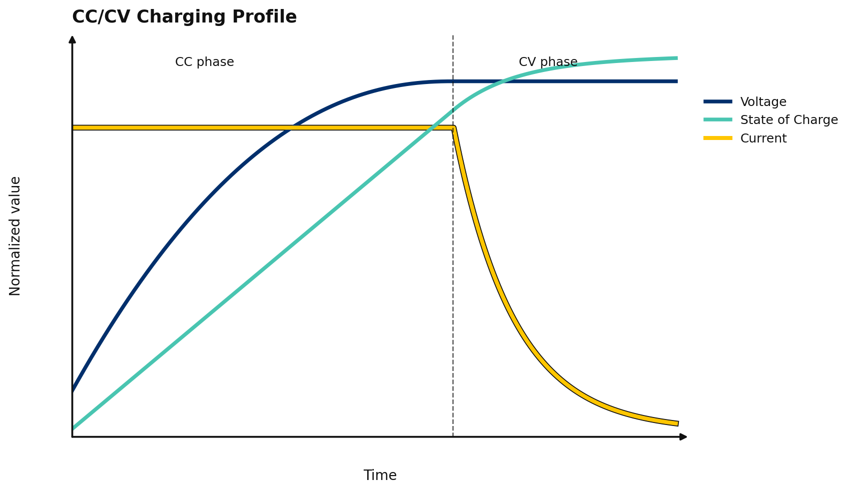
Constant Current / Constant Voltage, or CC/CV charging, remains the most common lithium-ion charging method because it is simple, well understood, and broadly compatible. In the constant-current phase, the charger applies a fixed current while voltage rises. Once the cell reaches its upper voltage limit, the charger holds voltage constant and allows current to taper until charge termination.
Why It Works
CC/CV succeeds because it provides predictable behavior in the early portion of the charge window and robust protection against overvoltage near the top of charge. It is straightforward to validate, easy to implement in BMS firmware, and compatible with a wide range of lithium-ion systems.
The tapering current in the CV phase also reduces stress near full charge, where the battery becomes less able to accept lithium rapidly. For many products, that balance of simplicity, safety, and manufacturability makes CC/CV the default starting point.
Where It Falls Short
From an electrochemical standpoint, CC/CV is coarse. It assumes that one current level is appropriate across wide variations in temperature, cell aging, and internal resistance. In reality, the optimal current at 20% state of charge on a warm, fresh cell is not the same as the optimal current on an aged or cold cell.
At low temperatures, diffusion in graphite slows significantly, which increases plating risk if current is not reduced. At higher state of charge, concentration polarization rises, yet traditional CC/CV does not proactively reshape current before stress accumulates. As the battery ages, the same applied current produces more overpotential, but the profile still behaves as if the cell were new.
CC/CV remains stable and useful, but it is fundamentally static. It protects with broad rules rather than adapting to what the battery can safely accept in the moment.
Step Charging: Discrete Control Across the Charge Window
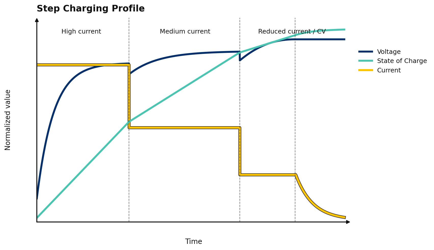
Step charging modifies the constant-current portion of CC/CV by reducing current in discrete stages as the battery fills. A typical profile may use a high current at low state of charge, then step down through one or more lower current levels before entering CV taper.
Why It Helps
This approach reflects an important electrochemical reality: charging does not stay equally easy across the full charge window. As the anode approaches higher lithium occupancy, diffusion pathways become less favorable and concentration gradients become harder to relax. By reducing current in stages, step charging can lower lithium ion flux, moderate overpotential, and reduce the likelihood of plating or excessive heat generation in later stages.
For OEM teams, step charging is often an attractive upgrade because it is still relatively simple to implement. It can deliver better fast-charge behavior than basic CC/CV without requiring a completely new control philosophy.
What It Still Misses
The limitation is that step charging remains predefined. It assumes the best transition points are known in advance and that all batteries will respond similarly. In practice, diffusion thresholds shift with temperature, aging state, cell-to-cell variation, and operating history.
That means step charging is more nuanced than CC/CV, but it is still open-loop control. It does not truly observe whether the battery has enough stability margin for the next step. It simply follows a better set of approximations.
Pulse Charging: Using Time Structure to Manage Polarization
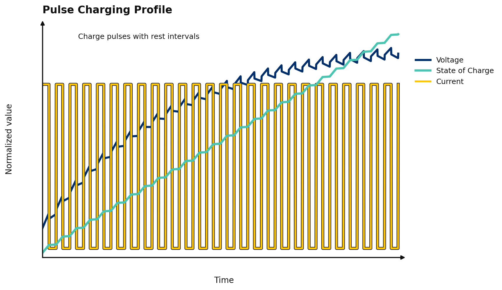
Pulse charging applies current in bursts separated by brief rest periods, and in some implementations includes more complex waveform shaping. The theory is that time structure matters: when current is interrupted, lithium concentration gradients and polarization may partially relax before the next excitation.
Why It Attracts Attention
From a physics standpoint, the idea is sound. Diffusion is time-dependent, so short rest intervals can give ions an opportunity to redistribute more evenly within the electrode. In the right conditions, that can reduce local stress compared with continuous high-current charging and can improve how the battery tolerates aggressive charge events.
Pulse charging is especially attractive in applications where fast charging is important but continuous high current creates unacceptable heat or degradation.
Why It Is Hard to Optimize
The challenge is tuning. If pulses are too short, relaxation is negligible. If rest periods are too long, charge time suffers. If peak currents are too high, local overpotential may still cross plating thresholds even if the average current appears reasonable.
Pulse charging can therefore be effective, but only when pulse amplitude, duty cycle, waveform shape, frequency, and rest intervals are well matched to the cell chemistry, temperature, and state of health. Without that alignment, pulse charging becomes another static approximation with a more complex waveform.
Hybrid Charging: Layered Logic for Real-World Packs
Hybrid charging combines multiple control ideas into one strategy. A hybrid profile may start with CC behavior, step current down at defined state-of-charge or voltage thresholds, derate current at low temperature, and adjust taper rules based on pack or cell conditions. Some systems also add pulse-like segments in higher-stress regions of the charge window.
Why OEMs Use It
Hybrid charging is popular because real products rarely operate under ideal laboratory conditions. OEMs need methods that work across manufacturing variation, field temperatures, different usage patterns, and warranty constraints. Layered logic makes the system more robust than a single fixed profile and allows teams to embed practical protection rules where problems most often occur.
In many products, hybrid charge control is a sensible compromise between simplicity and performance. It can improve thermal behavior, reduce late-stage charge stress, and support faster charging in regions where the battery can tolerate it.
Why It Still Has Limits
Most hybrid methods are still threshold-driven. They react to measured voltage, temperature, and state-of-charge estimates, but they do not truly infer the battery’s deeper internal response. That means the charger still relies on predefined decision trees rather than continuous electrochemical feedback.
Hybrid charging is often a strong practical step forward, but it is still largely rule-based. As performance expectations rise, those fixed thresholds can become either too conservative or too fragile.
Adaptive Charging: Response-Based Control
Adaptive charging represents a more meaningful shift in philosophy. Instead of enforcing a predetermined path, adaptive systems adjust current dynamically based on how the battery is responding in real time. The essential question changes from ‘Which profile should this battery follow?’ to ‘What can this battery safely and efficiently accept right now?’
What Adaptive Systems Observe
Depending on implementation, adaptive charging may use online resistance estimation, thermal modeling, impedance-related signals, state-of-health tracking, and analysis of voltage response under controlled current changes. The common theme is feedback. The system does not assume that all cells, temperatures, and ages behave alike; it looks for evidence in the battery’s present response.
That matters because charging is a dynamic process. As cells age, resistance rises. As temperature shifts, diffusion coefficients change. As packs accumulate imbalance and usage history, the same nominal state of charge may no longer imply the same safe current acceptance.
Why Adaptive Charging Matters
Adaptive charging can reduce reserve margin where the battery is healthy and increase caution where the battery is stressed. That enables a better balance between charging speed, cycle life, and safety than static profiles can usually provide.
It also creates the foundation for predictive charging, where the control system is not just reacting to present conditions but using richer response data to anticipate degradation risk before it becomes irreversible.
Iontra’s Perspective: Precision Charging as a Competitive Lever
Many conventional adaptive systems still lean heavily on relatively coarse signals such as pack voltage, temperature, and estimated state of charge. Iontra’s approach emphasizes deeper response visibility during charging itself. By shaping current deliberately and analyzing high-resolution voltage response under dynamic excitation, the system can gain better insight into how the battery is actually accepting charge.
That supports more precise current-density management, better control of overpotential near plating conditions, and improved alignment between electrical input and electrochemical capability across the charge window. For OEMs, the appeal is not just faster charging in isolation. It is the possibility of improving charging performance, cycle life, and differentiation without starting from a new battery chemistry or a full pack redesign.
In commercial terms, that matters because the winning products in these markets do not simply charge fast on day one. They keep charging well after hundreds of cycles, under a range of temperatures, and without creating avoidable warranty risk.
The Evolution of Charge Profiles
The progression from CC/CV to adaptive charging reflects a broader evolution in battery systems design. CC/CV prioritized simplicity and safety. Step charging introduced staged reductions that better approximate diffusion limits. Pulse charging brought time-domain control into the conversation. Hybrid methods layered multiple rules for practical robustness. Adaptive charging introduced continuous feedback and condition-based control.
The next stage is likely predictive charging: systems that use precise control and richer battery-response data to anticipate instability, not just react to it. The common requirement across all advanced strategies is better observability. You cannot optimize what you do not measure.
Final Thoughts
Charge profiles are not cosmetic variations in firmware. They encode how much intelligence the system applies to managing electrochemical stress. For engineering, product, and hardware leadership teams, that affects fast-charge capability, degradation trajectory, thermal behavior, safety margin, and warranty exposure.
CC/CV still has an important place. Step, pulse, and hybrid methods can all improve on the baseline in the right context. But the broader industry direction is clear: lithium-ion charging is moving from static profiles toward adaptive and predictive control.
For OEMs evaluating battery charging algorithms, the practical takeaway is simple. The question is no longer just how fast a battery can be charged. The more strategic question is how precisely a system can control charging stress while preserving long-term performance. That is where differentiation is increasingly being won.
If you’d like to learn more about Iontra’s charge control solutions, please reach out to us at info@iontra.com.
Frequently Asked Questions (FAQ)
What is the most common lithium-ion charging profile?
CC/CV remains the most common profile because it is simple, proven, and broadly compatible with lithium-ion cells.
Is step charging better than CC/CV?
Step charging can outperform basic CC/CV by reducing current in later stages of charge, but it is still based on predefined breakpoints rather than real-time battery response.
Does pulse charging reduce degradation?
Pulse charging can reduce concentration gradients in some conditions, but its benefits depend heavily on pulse design, cell chemistry, temperature, and state of health.
Why is adaptive charging important for OEMs?
Adaptive charging helps OEM teams balance charging speed, cycle life, and safety by adjusting control based on the battery’s present behavior rather than a one-size-fits-all profile.